Hello LFS People !
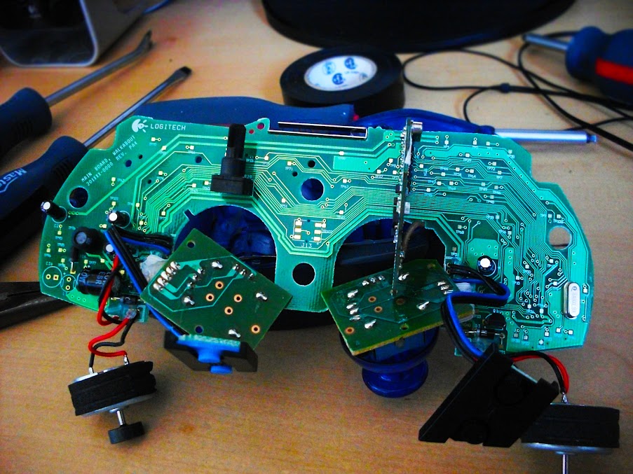
So, I've built an H shifter, with a clutch, about 3 months ago. It was working nicely until about a month ago, when nothing would happen when I was going through the gears. Nothing was detected. I did some tests, the part that failed was the PCB I used from a Playstation2 wheel. So... I decided I would change that PCB. So, Somebody gave me a Logitech wingman wireless gamepad . But there is a problem... The PCB on that is a nightmare. There is nothing identified, it's tiny to weld on, and... I don't know which side is the ground.
Can anyboy help me ? here are 2 pictures of the PCB, front and back.
Oh, if you wanna see the shifter, here's an album containing the progress
