
What I just described is quite similar to the particle swarm algorithm I experimented with for VRC at one point that used a neural network for each car. Instead of nudging k1 and k2 values for a steering controller like I just described, the neural network weights connecting all the nodes were the values that were adjusted (one value per link between nodes). So instead of two values (k1 and k2) there were a lot more, several per node to make up all the connections. Each one also had a velocity that told it how much to change each generation. I don't remember anymore, but there might have been an acceleration too.
It's been so long I don't remember what the inputs at the top nodes of the network were exactly, probably the same stuff like leftRightDistance and that kind of thing. The output was just two nodes: Throttle/brake (clamped between -1 and 1) and steering (also clamped to -1 to 1).
I'd suggest you rewind a bit and try what I described in the last post, starting with the hand tuned k1 and k2 numbers without any AI, forget about some "t" value based on a bezier curve and instead use simple line segments. Then I'd try a genetric algo or particle swarm algo to tune the k1 and k2 values to see if they can evolve to values similar to your hand tuned ones, or at least values that perform about as well in the end. Sometimes they'll come up with numbers different from what you'd expect that work even better than you could have tuned by hand.
After finding hand tuned (no AI) values, I'd plot the AI's values for k1 and k2 to the screen every generation so you can see how the numbers are actually changing from generation to generation so you can compare them to numbers that you know work reasonably well. Watching dots roaming around the screen isn't going to give you much insight into why it's working or not working. Who knows, they might be bouncing around between -885294 and 508345 or -0.00001 and +0.000001 every generation when they really need to be somewhere around -5 and -2, or they might be getting stuck or something. In that case it may become obvious why they aren't converging and the AI never makes it around turn one.
As for using something derived from that "t" value you're spending so many cycles computing iteratively, you might find the AI can learn to do what you want without it being computed very accurately at all. Perhaps you're following along with the iterative suggestion I described earlier? If so, remember that even if you started with a simply bisection (starting in the middle and then cutting it in half) every time, you're becoming twice as accurate every cycle. It doesn't take very many iterations to get to 99% accurate or so. I can't help but think that if that part is currently the main bottleneck, you might be going way overboard with the number of iterations. It ought to be dozens at the most probably, not millions.
From watching the top down racer prog run while writing that last post, it looks almost like you might have a bug somewhere because it seems the population just splits in two, one turning left and one turning right. The ones that turn right aren't being eliminated from the population, and none of the little guys seem to stick that centerline worth a darn. To me it looks like they just diverge and it just so happens that there's a left turn there so some of them are correctly turning left. If this were my program I'd be looking for a negative sign where it should or shouldn't be, maybe in a logic block. I.e., do you do something different if it's on the left or right side of center, because none of the cars appear to steer toward the centerline.
To get into AI like this I'd recommend starting even simpler than you're starting. Just run constant speed "cars" that use the segment approach described earlier where you have a cross track (left/right) distance as an input into a very simple steering controller like this:
steeringAngle = k * leftRightDistance
For starters I'd leave out the AI entirely and see if you can tune that k value by hand just to see what kind of number range you're looking at for it. Then you'll see it swerving a little bit so add in the damping with the leftRightVelocity, something like this:
steeringAngle = k1 * leftRightDistance + k2 * leftRightVelocity
I would see if I can tune that reasonably well by hand just to get the little cars driving a full lap. Nevermind if they're perfect or fast.
Once I had that, I'd reintroduce the AI whose sole purpose would then be to evolve k1 and k2 values. Nevermind the logic. You already have a genetic algo in place, so if you like that you might as well stick with it. I personally prefer particle swarm because it doesn't get stuck so easily and can change a bit more fluidly. In fact just as I write this, all of your AI's except for one suddenly began turning left and are slowing down for the corner. You might just need a higher mutation rate.
What happens in a genetic algorithm is that you might have a generation where all agents' k1 = 5 when it really needs to be -1.25. The only way it'll hit k1 = -1.25 is almost blind luck, a huge number of generations made even larger by a low mutation rate. With a particle swarm algorithm you might have a bunch of agents with k1 values like this:
k1[0] = 4
k1[1] = 5
k1[2] = 6
k1[3] = 7
In a particle swarm algorithm, the entire group has a "best ever recorded for any particle of all time" k1 value which is used to push all of the agents' k1 values in that direction. Each individual agent also has it's own best k1 value. The k1 values then are nudged in the direction of both of those best values (one best for group history and one best for individual agent history). Each k1 has a velocity which is also random, so all of the k1 values will change every single generation instead of getting stuck at k1 = 5 or something while waiting for a mutation to happen. Make sense? It converges a lot faster usually with stuff like this and is simpler to write than a genetic algorithm.
In this example, the k1[0]=4 value was the best of the group, so all of the values get pushed in that direction. It's been so many years since I've done this that I forget the exact computation (I'll look it up if you want it), but basically each of those k1's has a velocity too which changes a bit in the direction that pushes them all toward 4. So on the very next step without waiting around for mutations or anything you might get this:
k1[0] = 3.9
k1[1] = 4.5
k1[2] = 5
k1[3] = 5.2
Now you have a new group best, probably a few individual bests, and things keep moving in the direction of hitting k1 = -1.25 or whatever. Suddenly all of the agents have a decent chance of improving each generation. This group of values might be completely unique in the history of the population, and they aren't sitting there for 100 generations waiting for a mutation that might just set k1[0] = -5897345 or something equally useless. What if the range of k1 values that's actually good is just between 0.02 and 0.03? With a random population of numbers between 0 and 58945 or something you'll be waiting a very long time, and if the mutations happen to not allow two places after the decimal, it will never get there anyway.
Anyway, a genetic algorithm can still work, you just might see what I'm seeing where the simulation runs huge numbers of generations and basically gets stuck until a favorable mutation happens, and depending on how the controller itself is working you might never get convergence (maybe steering left is not really possible, etc.). With particle swarm every agent is pretty much nudged in the right direction every generation. At the same time every generation is unique from every previous generation, so it's like you get the randomness without worrying about how much randomness to build into the system. You don't have to fiddle with mutation rates and that sort of stuff.
Last edited by jtw62074, .
I tried your top down racer program. Neat. It's good to start simple like this.
First, a quick symmantic matter: The term "swarm" is used in particle swarm algorithms, not genetic algorithms like you're using here. Your group of cars is a "population" or a "generation," not a "swarm."
Ok, moving along. From post 391:
This description doesn't really say much to me about how the system is working. I assume your outputs are steering (-1 to 1) and throttle/brake (-1 to 1)? Something like this? What are your inputs? Is it the "t" value alone? Are you simply using the "t" value to come up with a new interpolated world position for a target point the car is chasing and this is all the algorithm is trying to evolve? The "t" prediction?
If you had a perfect "t" there's no guarantee the car would even know whether it should be turning left or right, so there's no point in trying to get that accurate to a zillion decimal places. You might be barking up the wrong tree on that one. If you can get more specific about how the controller is working, perhaps I can help, but it's quite nebulous at this point. Maybe it's time to post some code?
If a circle track racing sim only had "turn right" values available (0 to 1) and used the angular position of the right rear wheel to decide how much to turn right, it would never learn how to turn left, much less figure out when to use the brakes or throttle, regardless of the mutation rate or anything else. And because the angular position of the right rear wheel was used, it might just swerve left and right every time the wheel makes a revolution. That's not going to learn to do what you want because the wiring simply isn't there to do it. If the system isn't progressing, that's a sure sign something is fundamentally not right or there's a bug.
I'd think about trying to simplify that iterpolation stuff on the "t" value to speed this all up if that's really where all the work is being done. You might be overly concerned with the accuracy of the target point the cars are shooting for.
At this stage I'd suggest simply treating it as if there's a straight line segment between each reference point in the center of the track. You can generate those initial points with your bezier or whatever, but let the AI use simplified line segments connecting them all to chase after. Then use the car's relative position along a line perpendicular to that so they know how far to the left/right they are from track center. A cross and dot product or two should do the trick. Don't worry about getting 99.999999% accurate, you're just trying to find some basic wiring at this point. Compute it once very simply and forget the iterative stuff just to see if things start steering in the correct direction at some point at least.
Use that left/right "distance to center line" to compute a steering angle and forget the logic. You could also use the velocity component along that line to modify/damp it as I described earlier, but I'd start without it just to see if they at least start swerving back and forth across the centerline however chaotically. Make sure the distance to centerline computation comes out negative on one side and positive on the other so you can avoid logic flips like you mentioned.
I'd start by just picking the "current segment." When it gets close enough to the end of one segment you just switch to the next one. In fact you might as well just use the "next point" as a target. Either way, keep the cars slow enough so they can make the turns easily and just see if you can get them following that centerline somewhat well. I'm not sure, but it sounds like your learning algorithm is focused on that magical "t" point, as though if you got that point infinitely accurate the cars would all start turning left instead of right after a few minutes.
I just remembered something. This was all so long ago, maybe ten or twelve years, that I'm not totally sure what I ended up doing in the final product, but I distinctly remember a phase in developing the hard coded type of AI for VRC (not ANNs) where I tried to let the AI evolve its own throttle/braking algorithms so that it was actually learning on its own to an extent.
One of things I think I tried was setting the default throttle position to 100% so they were at full throttle all the time. With my hand tuned steering algorithm the car speeds would be too high to make it around most of the corners. IIRC, I detected this by checking the car position to see if it was too far off the path (prerecorded lines in my case). If it was, it tried again with less throttle, then less still, eventually adding some braking, etc.. This did eventually work and the cars could eventually lap the track at a reasonable speed, but it not nearly as fast as they could using prerecorded target speeds that were sometimes processed a bit more. It was interesting anyway and was my first attempt at doing an actual learning algorithm that was much simpler than an ANN.
In the "recorded target speed" system that went into the final product, I think I also had a conditional throttle algorithm that would go to 100% throttle if the car was going slower than the target speed. So you can try little tricks like this to speed up the cars more. However, in my case it was a little bit simpler. For that system I cheated a little bit with the tires, giving the rear tires enough grip that the AI could do anything it wanted with the steering and throttle and the cars would never spin, that kind of thing. In your case you'll have to work a lot harder than I did. However, the ANNs didn't need to cheat at all with the physics. They could handle an extremely loose car amazingly well, better than a human, and learn that in a matter of minutes.
The trouble you might find is that there are so many variables involved at that point with the slip angles of the tires or car and so on, that hard coding a solution for all that, let alone coming up with the myriad of constants for it, might prove a lot more difficult and time consuming than learning to do ANNs and writing a system for it. ANNs can be an enormous time saver once you've got them set up. They can do all the hard work while you sleep, really.
The look-ahead also helped the swerving oscillations in my case by having a point out ahead of the car to aim for. I found that the further this point was ahead of the car, the lower the oscillations. I imagine you've seen this in your own work. Try setting it to 0 look-ahead distance and watch the mahem that ensues.
I don't think you should jump into ANN's right away. Instead you probably ought to go ahead with the hard coded stuff for awhile like you're doing now so you get a feel for what ideas for control work well, what inputs might be useful and not, that kind of thing. Conceptually you need a good idea how the system is working of course, and for me the best way to go about that in the beginning is to try and do it all manually. Once I find myself thinking "if only the cars could automatically do this or that in order to come up with a good number for this variable and that one in order to tune my constants without me having to do anything," that's the time to start looking at ANNs. Also when you want to include a lot more variables than your brainpower will let you write a hard coded system for, ANNs can be a good solution. They can solve really complicated problems that humans can't really wrap their minds around. I'm fairly sure that's how facial/speech recognition software and all that kind of stuff works, and there's currently a competition project for the CERN particle accelerator to process their data to find Higgs bosons that uses machine learning. There's no way to write stuff like that manually probably.
Back to the ANN racing AI: Since I wrote the physics engine I could do whatever I wanted including running things in fast forward which just sped up the process. It would still work without that of course, it'd just take longer. It might be a deal where you just let the AI evolve overnight or have it doing all this on a separate machine while you check on it every hour or so to see how it's going.
In the original VRC that had the hard coded type of AI (not ANNs, that was done years later as an experiment that was never finished/released), I had some extra windows open with the constants so I could change the numbers while the cars were driving around. That worked well enough to make a commercial product with it and there weren't really very many constants. There were just enough so that I knew what each of them did, and by playing with them I got a feel for the numbers and could tune things well enough.
The swarm stuff: The way I did it, each "particle" in a swarm was an entire ANN. During a training session there were multiple ANN's evolving. You only need one car to do a particle swarm with multiple ANNs. I just swapped in and out the different ANNs into one vehicle after it finished a cycle (i.e., completed a lap or two or maybe ran for some fixed time period in the initial phase before they could do complete laps). So it was only one car on the track every time that was using one ANN, then switching to the next ANN, etc.. After all the ANNs had taken their turn, it would adjust the weights and start over.
What I did need to do though in the first phase before they were smart enough to run a lap was be able to reset the car positions/speeds and so on to some initial condition for the next ANN run. If you can have the software do that in LFS automatically then you might be good to go. It might also be possible to train the AI on a recorded run at first just so they could start the main learning process already able to do laps, but for me it seemed like a lot more work and wasn't really necessary, so I never bothered with that.
BTW, I don't think ANNs are particularly common in racing AI, so if it ends up turning you off, I wouldn't worry about it too much. One can make a pretty good AI without letting things go to the abstract black box level with ANNs. Just because it's an ANN doesn't necessarily mean it will be better than a well thought out traditional AI anyway.
If you do ever get to ANN's, let me know and maybe I can help out with some of the details. I've enjoyed watching you post on all this over the years and seeing it develop. I'd be happy to have some correspondence with you on this if you get stuck or want to bounce ideas off someone that's done it before.
You're talking about a tangent point here, basically. Indeed, there may not be a way to compute this exactly (I could never figure it out either), but you might be able to get a reasonably good estimation by doing some iterations. I've never worked with Bezier curves so can't help you there, but with Hermites the input was basically a value from 0 to 1 representing the normalized distance between the two end points on the curve, which would spit out an x/y point that is actually on that curve.
That's not the exact point you're looking for but most of the time might be close enough. That could be extended into an iterative scheme where you score that x/y point by comparing it to the car's actual position, then trying another value (for the 0-1 input part) based on that. An easy way to do it would be simple bisection where you just start at 0.5 (or some better approximation), then either go to 0.25 or 0.75, then if it was 0.25 then you go half way between 0.25 and 0.5, etc., cutting it in half each time. Eventually if you get a point on the curve hopefully that you can do a computation on that says "this point is close enough" and just use that as the closest point on the curve. It won't be perfect, but neither will the steering/brake/throttle algos, so it probably won't matter. "Close enough" can get you a long way.
That's how my VRC code worked too if I remember right. Conceptually I was imagining the AI asking "where will I be x seconds from now," then using that point on the curve as a target of sorts. Same thing you're doing in principle, really. To stop the weaving I had to add a damping term to the steering algorithm that used the left/right velocity toward or away from the path. This wasn't real hard to tune either, there was a pretty wide range that worked reasonably well and would stop the weaving. If necessary you could also code in some hard limits, say if the distance is really big (after a crash or whatever) then it might not damp it at all, things like that.
So basically it was something very roughly like this:
steeringAngle = someConstant1 * (desiredCarHeading - actualCarHeading) + someConstant2 * velocityTangentOfPath
You could also add in power constants to tune this more, something like this:
steeringAngle = someConstant1 * (desiredCarHeading - actualCarHeading)^somePowerConstant1 + someConstant2 * abs(velocityTangentOfPath)^somePowerConstant2 * sign(velocityTangentOfPath)
Then there were more terms added to deal with other nearby cars, basically. I think in the actual code I ended up breaking these all into separate terms to clean it up so in the end I could just go like this:
term1 = something
term2 = somethingElse
term3 = somethingElseAgain
steeringAngle = term1 + term2 + term3
That kind of thing.
Regarding throttle, each of my curve's node points had a target speed for the car which was recorded by my own driving in slow motion attempting to do perfect laps. This could be scaled up and down a bit for difficulty levels that the user chooses and worked very well so long as the car was actually capable of making the turns at those speeds.
Throttle was then a simple matter of doing something like this:
throttle = someThrottleConstant * (desiredCarSpeed - carSpeed)
Or using a power constant something like this:
throttle = someThrottleConstant * abs((desiredCarSpeed - carSpeed))^somePowerConstant * sign(desiredCarSpeed - carSpeed)
Neural networks
What I have above is probably pretty similar to what you have. You might have even more terms than this, but I just wanted to show you the basic approach and thinking that worked quite well in VRC back in the day. What a neural network does is turns those equations basically into a black box, so your curve and whatever other information you want goes in on one side while throttle and steering come out on the other. The trouble with this is you can't just tuned it all by hand like you can with the other approach which is a simple matter of adjusting the constants and observing what they do to the car. Instead you really have to let it just learn by itself by trial and error.
If you get interested in this I might be able to point you in the right direction. Most of the stuff on ANN's online is unnecessarily complicated for this kind of task. There's all kinds of learning algorithms, back propagation and so on, discussions about how to limit the weights and initialize them, on and on, but really there are much easier ways to get good enough results and much of that can be ignored in the end for an application like this, so don't let it intimidate you. I hardly understand half the ANN stuff I've read. When I experimented briefly with an ANN driven car, I initialized weights with totally random values, unrestricted (not necessarily between -1 and 1 or 0 and 1 or whatever), then just used a particle swarm algorithm to adjust the weights using a very simple fitness scoring mechanism:
In the beginning before the cars were smart enough to drive a lap:
fitnessScore = distanceTravelledAlongPath
Then once they were smart enough to lap the whole circuit, it was changed to something like this:
fitnessScore = 1 / laptime
So the faster an ANN went, the better score it received and the weights of all the ANN's in the system were shifted a little bit in that direction via the particle swarm algorithm rather than some enormously complicated backprop nonsense. Rinse, wash, repeat, and the ANN's all evolve to become really fast. It worked pretty well.
One neat thing about this is that you can in priniciple use any kind of inputs you want, vehicle slip angle, understeer gradient, yaw velocity, etc., maybe even the previous cycle's steering and throttle could be inputs too, in addition to whatever path information you want to use. You can add so much stuff that a human would never be able to try and write a useful equation such as in the non-ANN case and tune all the constants. You let evolution take care of it instead because it often does a far better job than a human ever could, and it does it much faster.
It's also really fun to watch the learning process evolve. Even if it doesn't work as well as you hope, it's a fascinating thing to see and gets you really thinking about real biological evolution.
Another way to do the weights in the ANN is to use a genetic algorithm. I've tried this too in an ANN, but not for a car driver. I think a particle swarm system will probably work better in the end anyway, and it's a lot easier to write and wrap your head around. KISS.
Last edited by jtw62074, .
I used hermite splines in the VRC AI years ago. I don't think I used tangent/forward vectors and normals, but they shouldn't be too hard to estimate from hermite splines because two of the four inputs are forward vectors to begin with. Anyway, that could be an option for you if it turns out to be too hard to do with the Beziers.
That's a mighty wide brush you're painting with there. :duck:
Racing and a love of driving just isn't as big here in the US. I've spent a couple years in various parts of Europe, and the percentage of people that are racing fans or liked to drive fast seemed a lot higher than it is back home.
I haven't met anybody in the US that's heard of LFS, rFactor, iRacing, Assetto Corsa, or any of them. Mention Forza or Gran Turismo and even the people that don't care about cars in the slightest know it. Advertising?
Carl:
What I did in the original VRC was even simpler than that: Make a path which is a bunch of points with a direction vector (2D only) at each one to describe a hermite spline. Each point also has a target speed the car tries to maintain. Compute the distance the car is away from that path and use it as an input to the steering controller. Do the same for velocity in the cross track direction, i.e., how quickly you're moving left or right of the path. This way it's following a curve rather than racing from one point to the next and making sudden steering changes at each point.
The steering controller would then get modified further depending on nearby traffic by trying to maintain some distance to the left/right of the nearest car. Throttle/brake was a simpler controller and just determined by the target speed versus current speed for the most part. There was a bit more to it but that was basically it.
There were multiple paths recorded by me driving fast laps in slow motion which turned out to be a good way to get really good laps in our R/C car sim. Every lap the car would choose a new line at random so the cars weren't all doing the same thing every time.
I did cheat a little bit, the physics were simplified a little bit. The tire model was much simpler, there was no drivetrain model for the AI so the longitudinal tire forces could be controlled directly with the throttle. This meant no yaw moment changes due to the diffs or solid axles, so it was almost like a built in stability control system. Add a bit of tire grip and lower the center of gravity and voila, they could beat most drivers around the track.
Blackbird:
Now you're perhaps getting a peek at some of the issues I was talking about. The hardest part of all this is making the cars drive where you actually want them to, hence you'll find there's probably no point in trying to model the human error aspect of it. I spent a lot of time on that and never got it as good as I wanted, and that was with physics that cheated a little bit on the AI side. Doing the same thing on a full vehicle model is a substantial challenge. I haven't driven LFS in a long time, but from what I remember, Scawen did a really great job on his AI. Bet I could learn a thing or two from him in that department.
I understand you're not adding error now, but are just thinking about it for later.
It's good that you've gotten it driving. You've no doubt seen what I mean about adding error into it making things that much harder to control. The AI will be error prone right from the start because it's tough to get them to do what you want anyway. I spent a lot of time just tuning the steering controller in my system in order to minimize path following errors as much as possible. Making it drive sloppy is relatively easy. Being accurate is a lot tougher as you're probably finding out.
It's good that you've gotten it driving. You've no doubt seen what I mean about adding error into it making things that much harder to control. The AI will be error prone right from the start because it's tough to get them to do what you want anyway. I spent a lot of time just tuning the steering controller in my system in order to minimize path following errors as much as possible. Making it drive sloppy is relatively easy. Being accurate is a lot tougher as you're probably finding out.
As far as introducing error on purpose goes, I found that I couldn't get my own AI to be how I wanted it even without any error. I.e., my own error found its way into the AI all by itself and made it worse than I wanted it. Adding more error may be an interesting exercise because you're mimicking a human, but as someone else wisely pointed out, if the error is not modelled the way real human error works, it's kind of pointless. If you're worried about making AI that is too perfect, well... It's not likely to happen. Quite the opposite in all likelihood.
If the AI is running 100 cycles per second or something, what are you to do really? Randomize some error into the driverA/driverB positions? If so, how much error and how often do you randomize them? 100 times per second? 10? 1? Do you do it the same twice in a row or do you give the error some velocity? And is that how perceptual error in a human works? Modelling the human error could probably be categorized as an entire field unto itself.
I don't want to discourage blackbird if he's having fun, but at the same time, one thing I've learned is that there's sometimes a fine line between taking on a big challenge and biting off more than I can chew. Keep at it if you're having fun, but just realize you haven't gotten to the really hard part of all this yet after 5 or so years of tinkering with all this: Driving a race car at a human's pace. I'd get into that as soon as you can so you know if you even want to continue with AI after seeing what needs to be learned on the vehicle dynamics side to do it reasonably well.
The AI system I wrote for VRC around 10-12 years ago used the lateral distance to the nearest car as a modifier into the steering controller. Basically the steering controller would try to follow a path by adjusting steering based on how far away it was from the path along with velocity (basically like a spring/damper). IIRC I added another term to deal with the nearest car, so it would turn toward the desired path, but if another car was close enough it would turn away. Once it got far away enough from the path it would stop trying to move over further, otherwise they would just run off the road when you came sailing through and not put up any fight.
Throttle/braking was done in much the same way. There was a target speed at each path node. It was basically just a simple P controller at the core if I recall correctly, but then it'd modify it if it was behind another car so it wouldn't ram into the back of it (usually).
I was pretty happy with it and proud of it, but a lot of players hated it. I remember one guy insisting the black car was out to get him, that it was much more aggressive than the rest and so on. Wasn't true at all, the physics engine didn't know or care which car was which. I think what happened is he probably got too close to it in the wrong spot on a track once or twice which caused it to react to him differently than he was used to. From there on out he behaved differently around that car which then caused that AI to react differently to him. In essence he gave it the bad personality he was ascribing to it. I got a kick of that one.
Unfortunately I think blackbird has got a really long way to go here even though it's pretty cool what he's doing. It's an interesting experience and for sure educational, but the hardest part is still ahead: Making a car drive competitively. Making one putter around a track at 25mph is easy. Making one that can get lap times as good as most humans is really hard, especially if you don't cheat a little bit by giving the AI more tire grip or something like that. I had to cheat in VRC a little to make it fast enough for the top guys.
Eventually I ditched the AI and do not plan on doing it again. I learned the hard way that life is just too short for that nightmare. I wish blackbird luck anyway.
Two tires crossing over each other like you see in the plot isn't the problem. That just means they have different spring rates which is to be expected seeing as they're two different tires. It's virtually impossible to make two different sized tires have exactly the same spring rate.
It's interesting to see but it doesn't say anything about the goofy data set. That is only visible when you plot the same tire at several pressures and find the slope reverses direction at the one pressure.
I would still suggest that if that data is correct, the anomaly might be due to the tire changing shape suddenly at some pressure rather than the cords becoming less stiff at the higher pressure for no good reason. Think of it like a spring inclined in a suspension system. A stiffer spring inclined at a larger angle could give a smaller effective rate in the vertical direction just because it's inclined. I.e., an infinite rate at 90 degrees to the axis you're interested in means a rate of 0 lb/inch in that direction. Similarly, a change in carcass shape might produce the same result through the cord angles and so forth being different in the ground's reference frame. To me this seems like the most likely case aside from the data being a bit dodgy to begin with.
There's plenty we don't know about the details of the test too. Maybe the temperature changed a lot, or maybe they tested the first few pressures, then switched tires, then switched back to the original tire and tested at the final pressure. There are a lot of possibilities here for this kind of thing. I've seen weird things like that before in lateral force vs. slip angle tests where the results would mislead you into thinking a tire had reversed load-mu sensitivity. It happens more than you'd think.
Here's an example of a set of load versus vertical deflection curves:
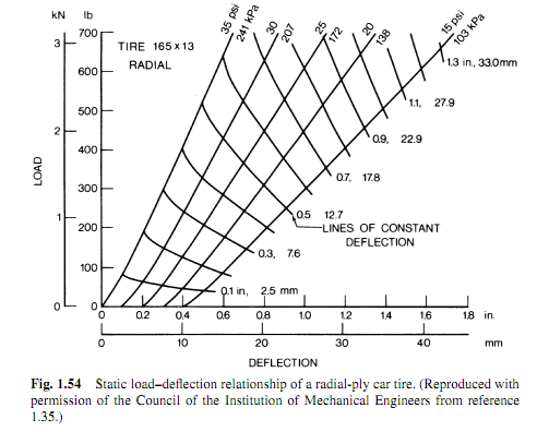
The lines moving up and to the right are pretty close to being a constant slope, with the slope being different at different pressures. Usually near zero load you'll see a little change in slope, but when you're just interested in the characteristics at the loads the tire normally sees when it's on a vehicle, that part is not really touched anyway so it's not real important.
Sometimes you'll see graphs like this that show load versus contact length instead of vertical deflection. These are more akin to load versus gross contact area, so if I were to rewrite that article today I would just use those data. To show that the contact area = load / pressure formula was wrong you could just show it in the slopes of the lines. I.e., doubling the load doesn't increase contact length (and therefore the approximate contact area) by 100%, it's usually closer to 50%. That in itself would have made the point and done it with a lot less rambling. :rolleyes:
The important thing to note from the load/deflection curves is you never see what the Avon tire showed. For that to happen the lines moving up and to the right would have to curve sharply back to the left at higher loads. I've never seen it any data of this kind or anywhere else. So it was just dumb luck that I happened to pick a pair of tires for that article where one of the tires either really did that, or just had bad data. I'm inclined to think the latter was the case.
Last edited by jtw62074, .
Interesting idea. I don't know for sure, but wouldn't think that's the case. This is a bit like saying that if you blew up a balloon there might be a point where the tension in the balloon decreases.
The strength in the tire isn't so much the rubber, it's the cords. When the internal pressure is increased, those cords go more into tension which increases the stiffness, hence the increased spring rate you get. My thinking of the strange Avon case was that maybe the shape of the tire changes in such a way at some point as it's being inflated that it becomes softer in the vertical direction. I don't know, but when I was trying to think of a reason at some untuitive level why this might occur, that's what went through my mind. It could be nonsense though. To really know you'd have to do an FEM analysis on it or test it again to really make sure.
I personally suspect there may just be an error there because it's the only tire I've ever seen data like this on where it appeared to happen. Paul Haney's book "The Racing and High Performance Tire" shows what looks like a rougue data point in one tire that he thought might have just been bad data too. I've seen some questionable data before on other things showing backwards load sensitivity from Michelin and that kind of thing, so it's not out of the question.
I did think later of rewriting that article to make the same point with a tire whose test results are more typical, but I was just writing the article for my own amusement and didn't really care to bother with it by the time I was done. In the end there were two tires there, one that was goofy and one that wasn't, so I just left it to show that things are not always as expected. I honestly never expected anyone to see the article anyway as there's no link for it on my site, but Google being what it is, I get 400-800 hits on it every month anyway.
When it comes to sims, a linear vertical model works well enough usually as long as you allow the spring rate to change with pressure. That covers the general effects described in the article well enough usually except for the part where the tire started sinking at still higher pressures. So that'd be the only part that's probably much different from LFS, and it's a fluke or mistake anyway so I wouldn't be worried if LFS didnt' do that. If you want to go further with it you can make it change with slip angle/lateral force and/or camber, that'd be more interesting than having a freak tire that does what the Avon tire appeared to do.
Neat idea, that possibility never occurred to me. If you ever get time to let me know how it works I'd be interested in hearing about it. Maybe I could make a version that's for one of those sims. Probably would get a lot more downloads than I'm currently getting. :rolleyes:
Yes, I'm pretty sure I remember seeing it too in a slow motion video. Don't really know for sure though.
Carl, the data on that page was copied correctly from the tire data supplied by Avon, so if there's a mistake in it, it's Avon's. If you read the full article you should see that I was just as surprised by the results as you are.
I wrote the article probably seven or eight years ago. Since then I've realized there are much easier ways to check the contact area formula and show how wrong it is. It may help you to know that this is the only time since then that I've seen data showing a result like this where reducing pressure caused the resting radius to go in the opposite direction you'd expect. Normally it's just what you would think: Reducing pressure sinks the tire down rather than the opposite. So we can't rule out the possibility that the data from Avon was incorrect.
Not sure I understand the question. Perhaps you might be overthinking it?
When it comes to vertical motion and tire contact load, you can think of a tire as being a simple spring extending from the center of the tire to the ground. The spring rate changes with air pressure a great deal, and to a lesser extent it changes with camber and load. Generally in vehicle models the assumption is made that the spring rate is constant at each camber and pressure and doesn't change with load. If you plot out tire deflection versus load it's usually a pretty straight line once you get up into loads the tire normally sees. At very light loads it can deviate from this a bit, but it's not of much consequence to the car so you're generally safe ignoring that.
In that sense LFS is probably just fine. I don't know if the spring rate changes with load or pressure in LFS. You could test this by going between full and minimum pressure and see if it changes the ride height of the car and the vertical deflection of the tire. I would bet that it does it just fine in LFS, but am not 100% sure. Maybe the link Daniel-Cro posted might show it?
Whether or not LFS follows the simple formula discussed in my article, I don't really know. If it's using a set spring rate for each pressure and camber or whatever, then it might not. It might be of no consequence either way unless the in-plane tire forces are computed from the contact length. Your guess is as good as mine there though, I don't really know.
Last edited by jtw62074, .
What's the AIRS world coordinate system, or should I not be concerned with it?
Not sure if you'd want to consider this next one as it may be very much outside what you had in mind, but this sounds like a prime candidate for a neural network driver. Years ago I wrote one of these that was trained by a particle swarm algorithm (back prop algos and stuff confuse me, particle swarm is 100 times easier). It was a path following system , but the steering controller was controlled by the neural network. Pretty sure the throttle/brake was too but I'm not 100% on that.
It was cool and actually worked pretty well. I'd run everything in super fast forward to move things along. Starting with a bunch of totally random brains, it'd have a few seconds to get as far as it could around the track. It'd score it, try the next one, wash, repeat. They'd bumble around for awhile but eventually one one zoom down the first straight and crash in turn one. Then another one would do it a little later, then more of them. Eventually one would get through the corner and zoom into the next. Every now and then one would just take off like a bat out of hell and run around the whole track. It didn't even need to learn all the corners. It was doing it just using the next few dots that were coming up. How they were spaced, etc.. Once they were all making laps I think I had it start scoring them based on lap times so they just kept getting faster and faster. I seem to remember them eventually getting very close to human best laps. Unfortunately I had stop after three days of development on it and go work out of the country for a month, so I never touched it again. It was fascinating to watch though.
This is somewhat similar to what you might have in mind where the AI doesn't actually know what corner it's in, what direction it's facing, or what is coming next. It just sees a bunch of dots. Granted, you'd be dealing with a lot more information (I think mine was chasing two or three dots at the most), but I bet it'd work if you're feeding it a bunch of nearby reference points forward in Jared's field of view. It'd just take time to let it train and you'd have to score their fitness differently. Off road excursions might not work so well because how do you train an AI to figure it's way back to the track, but you could switch to something else there if you wanted.
I tell you what though, there is no way I could have tuned the steering controller that well by hand. The computer learned to do it better through evolution than I could ever do it in about five minutes. You could give them an impossible car to drive, something very loose, and they would actually learn to drive it and be drifting around the track. It was almost spooky to watch it sometimes...
Last edited by jtw62074, .
Ok. You might need to bring me up to speed on how some of this works. I haven't read too much. Basically you have all the relevant information that LFS has, you've got the matrix and position and all that. What you're trying to do is make a basically blind AI that figures it's way around the track without using that position directly, right? You have the position because LFS has the position, but you want the AI to figure out the position on its own using only your sensors. That sensor data is itself produced by the LFS fed position/orientation. Am I following you correctly?
The visual sensor knows everything including the position and orientation so it can produce the visual information Jared sees that comes in as reference points in Jared's reference frame (driverA, driverB, etc..). Jared then needs to determine the car's world position on his own using only the information the visual sensor provides. Is that right? Ultimately in your best case scenario you wouldn't even want Jared to know the orientation of the car? He would basically see a bunch of dots and through the visual sensor only knows the distance/angle to them and makes his decisions that way?
The visual sensor knows everything including the position and orientation so it can produce the visual information Jared sees that comes in as reference points in Jared's reference frame (driverA, driverB, etc..). Jared then needs to determine the car's world position on his own using only the information the visual sensor provides. Is that right? Ultimately in your best case scenario you wouldn't even want Jared to know the orientation of the car? He would basically see a bunch of dots and through the visual sensor only knows the distance/angle to them and makes his decisions that way?
Last edited by jtw62074, .
This is what my italicized paragraph in there was talking about. All you need to do is a cross product on the forward and right vectors you created originally from the 0,1,0 vector. This gives you a fourth vector which is now "up" relative to the car and you throw away the original 0,1,0. You now have up/down/right vectors (a rotation matrix).
If this needs to work when the car is pointing almost perfectly straight up or down and you do not want to use the entire LFS matrix, you can do a dot product check before all this to get the angle between the driver's eye direction and that 0,1,0 vector, and if they're too close to the same (lined up with each other) then you just pick another vector to use. If you can get the normal vector of a ground triangle under the car you could use that, or you could just switch the 0,1,0 to 0,1,0, or 1,0,0 and use that. You might need to take care to make sure "right" and "up" are not flipped too, but unless you're driving up a wall or around a loop you'll probably never need this check. You'll run into gimbal lock somewhere with this approach if you're computing your own matrices from a single forward vector, but cars using AI usually don't point straight up or down so it probably won't be a problem.
Either way you need orientation represented somewhere. If building the matrix is too much hassle then you might as well use the LFS matrix which won't ever have a gimbal lock problem. LFS probably uses a 4x4 matrix like other games, so just grab the first 3x3 elements.
What you use in the end depends on what you are allowing the AI to use for information of course. Maybe you want to provide it with only minimal data like a compass, something that's found in the real world, and let the AI compute what it really needs even if it's already available in LFS. I can understand that.
The trick is to try not to use trig to solve everything like you're doing. I avoid sine/cosine and all that except to actually rotate something. When I go from one coordinate system to another, I think of everything as points that are just rotated and moved. They're usually either rotated first and then moved, or moved first and then rotated, or sometimes moved first, then rotated, then moved back at the end. So just think "move, rotate, move" when you want to rotate something. You can rotate something forward by multiplying by a rotation matrix as you already know probably, and you can reverse the rotation by multiplying by the transpose of that matrix. That's about all you'll ever need with matrices.
It looks to me like you have 2 spaces: "world" and "driver." Is that right? So driverA and driverB are the positions of points A and B relative to the driver in his own coordinate system. worldA and worldB are the positions of those points in the world coordinate system. Am I following you?
In other words, if your driver was sitting still with 0 velocity somewhere and spinning around in circles, worldA and worldB would never change, and driverA and driveB would move in circles around the driver the same way a driver would see it out his window. Is that right?
So basically you are starting with worldA and worldB and are pretending to not know the car position because you're trying to get the AI to figure out where it is based solely on those two reference points, and you want it to do that regardless of what direction the car/driver is facing. Is that right?
You then want to compute driverA and driverB in the driver's coordinate system, meaning how it looks out his window. So if point A is 20 units directly forward of him, driverA = (0,0,20) (or whatever it is in your coordinate system) regardless of what direction he's pointing. Meanwhile worldA could be anything. You then want to feed that to your AI and have the AI figure out the car's world position knowing only worldA, worldB, driverA, and driverB. Is that right?
Does the driver have a compass? Does he know what direction he is facing? I read that you're reading the rotation matrix but I'm not sure what information you want the AI to have. Is a compass ok? Does he have the forward vector of the car perhaps?
If so, you don't need two reference points to get the car position, you only need one. All you should need to do is rotate driverA in the opposite direction of the car, then shift it. If you're using the rotation matrix of the car/driver then you just multiply driverA by the transpose of the rotation matrix like I showed before. If he has a compass and you're basically treating it as 2D, you can just rotate by the heading angle. So for example in world coordinates the point might be 20 units north of the car. The car is rotated 45 degrees to the right, so driverA = (-17.07,0,17.07) or something depending on your coordinate system. Just rotate that point by the opposite of the heading angle to swing it back around to line up with the world coordinate system again. Do this in other variables so you don't mess up driverA since you might need it later for something else.
I'll just do it in 2D with a compass heading assuming your up direction is "y" to illustrate the basic idea. In 3D you'd just multiply by the transpose of the rotation matrix to rotate the driverA and driverB points to unrotate it. Let's see if I get this right:
------------------------
rotationAngle = -heading //Note the negative sign so it rotates the point in the opposite direction which will undo the heading of the car.
//To make it cleaner for this post I'll assign 2 temporary variables like this:
x = driverA.x
z = driverA.z
//Be sure to convert the angle to radians for these functions calls.
s = sin(rotationAngle)
c = cos(rotationAngle)
xnew = x * c + z * s;
ynew = -x * s + z * c;
------------------------
xnew and ynew is your original driverA point, but rotated back to what it would have been if the car was pointing north. If the car was at 0,0,0 this would just make newA= worldA. If your car is not at 0,0,0 then newA will be shifted off of worldA by some x/y/z distance.
In other words, if this new point landed exactly on top of worldA, you would know the car position is 0,0,0. If it landed 10 units to the left of that, you would know the car is 10 units to the right of worldA. All you should have to do then is a subtraction using this new point and the worldA point and presto, there's your car position.
Last edited by jtw62074, .
Still at it after five years, I see.
I think what you're doing is pretty cool. I've been doing this professionally now for about 14 years including an AI system or two, and must say that it's pretty rare to see somebody doing what you're doing. I've written an AI system too, and you probably could not have picked a more difficult challenge. AI is hard and judging by your video you're doing a great job so far.
I haven't read the whole thread, but seem to remember when you were starting out on this. I'm looking through post 316 from last Wednesday and it looks like you're using trig to solve everything instead of using rotation matrices and vectors. Using those you can solve everything in 3D and a lot of the stuff it looks like you're trying to do may become a lot easier. Have you looked much into these yet?
There are few basic operations that can help. Forgive me if you know this already, but with all the sines and cosines I see in post 316 I'm thinking maybe this might be new for you?
If you want to compute the angle between two 3D vectors, you can just compute the dot product of it like this:
dotProduct = Vector1.x * Vector2.x + Vector1.y * Vector2.y + Vector1.z * Vector2.z
This gives you the cosine of the angle between the two vectors. For your purposes this may be enough if you're doing steering and so on based on the angles. The actual angle in degrees or radians may not be important to you. If it is, you can just do an arc cosine operation to get it in radians:
angleRadians = arcCos(dotProduct)
Not sure what language you're using, but it will probably have an arc-cosine function to do this somewhere if it's doing trig. If not, you can compute the arc-cosing using other trig functions. Will leave that up to you to Google.
What I would probably end up doing in your case is build a 3x3 rotation matrix for the car if you aren't able to pull that matrix directly from LFS. A 3x3 rotation matrix is really just 3 vectors grouped together that are always perpendicular to each other. The driver's forward vector you describe is one of them and points forward. Another vector points up, and another vector points either to the right or left depending on your coordinate system.
You need a forward direction vector (normalized to length 1) to start with which it looks like you already have (driver or car forward vector, I'll just call it "car forward vector"). To build the rest of the matrix I bet you can cheat a little bit since the tracks are pretty flat and just assign an "up" vector that's always 0,1,0 (or whatever it is in your coordinate system).
Next, you construct a new vector that's perpendicular to that "up vector" and the car's forward vector. You do that with a cross product operation. A cross product of two 3D vectors works like this:
Result.x = Vector1.y * Vector2.z - Vector2.y * Vector1.z
Result.y = Vector1.z * Vector2.x - Vector2.z * Vector1.x
Result.z = Vector1.x * Vector2.y - Vector2.x * Vector1.y
"Result" is a 3D vector just like you're car's forward vector is, but this one is perpendicular to the other two. Since your other vectors were "forward" and "up," this one points to the right or left side. For now I'm going to call "result" the "right" vector.
To keep things simple and see if this is at all interesting to you, I'm going to skip something here. Really what you'll want to do at this step is create another vector or two. This will allow your driver to see in actual 3D and remove the simplification that I made where we assume "up" is the same in the car's space as it is in the world's space. It would replace that first 0,1,0 vector we made with a new "up" vector that points up relative to the car instead of the world. With this, if the car is rolled at a 52 degree angle or going around a banked turn or down a steep hill or something, the reference points you describe will move up and down and spiral all correctly from the driver's perspective. You won't scratch your head anymore over the directions and relative orientations of any of this anymore, and you won't ever use another sine or cosine unless you really care how many degrees are in an angle for some reason. Maybe you use it as an input into your steering controller, but you could probably use the dot product instead. Anyway, I'll save this for later in case this all interests you. It's just a couple more quick steps that would go right here. The important part here is that you create 2 more vectors in addition to the forward vector you're already using. For now we'll just move along to the next bit.
Now you can just stuff those into a 3x3 matrix by stacking them into a structure something like this:
carRotationMatrix.x.x = ForwardVector.x
carRotationMatrix.x.y = ForwardVector.y
carRotationMatrix.x.z = ForwardVector.z
carRotationMatrix.y.x = UpVector.x
carRotationMatrix.y.y = UpVector.y
carRotationMatrix.y.z = UpVector.z
carRotationMatrix.z.x = RightVector.x
carRotationMatrix.z.y = RightVector.y
carRotationMatrix.z.z = RightVector.z
This is cool because now you not only know what direction is forward, you also know just as accurately what direction is up and what direction is right! You could have your AI controller react to something above or below you, or even tell if the car crashed and flipped upside down or something. It also may come in handy if you want to make a flight simulator some day and have your aircraft do stuff in 3D.
When you want to rotate some point into the car's coordinate frame, you just multiply whatever point you want to rotate by the transpose of this carRotationMatrix. For example, if you knew reference point A in world coordinates, but you really wanted it in the car's coordinate frame since that's where the driver is seeing everything, you multiply point A by the transpose of carRotationMatrix. Probably what you'll want is a function something like this:
referencePointRelativeToCar = Transpose(carRotationMatrix) * referencePoint
I do it a little differently than this, but you could do it this way probably if you wanted to.
What's the Transpose()? I used to just write out the entire computation in my code over and over every time I used it so it would get burned into my brain. I use a function or a function macro that looks like this:
Transpose:
Result.x = InitialVector.x * Matrix.x.x +_
InitialVector.y * Matrix.x.y +_
InitialVector.z * Matrix.x.z
Result.y = InitialVector.x * Matrix.y.x +_
InitialVector.y * Matrix.y.y +_
InitialVector.z * Matrix.y.z
Result.z = InitialVector.x * Matrix.z.x +_
InitialVector.y * Matrix.z.y +_
InitialVector.z * Matrix.z.z
That's the math for it. This looks like a lot but it's actually very fast. What is somewhat slow computationally are the sine and cosine operations, so I try to avoid those whenever I can. Note that right now we have an angle and have computed two other direction vectors that are all perpendicular to each other without using sine or cosine at all. So much easier. I still use sine/cosine in some places where there isn't really any other choice though, so don't worry about it too much.
Anyway, at the end of this you have referencePointRelativeToCar. This is sweet because now a coordinate like (1,0,0) tells you that the reference point is 1 unit left of the driver relative to the car regardless of what direction the car is pointing in the world. It could have crashed into a wall and flipped up on its front bumper, rotated 87.254 degrees around the roll axis and you would know that point is 1 unit left relative to the driver's point of view. Just imagine the possibilities...
This matrix and vector stuff is incredibly powerful. I used to do everything with sines and cosines too, and once I started learning this stuff things got a lot easier and I never went back. Beginning 3D graphics books and web sites will cover the big important ones that you use all the time: Rotation matrices, cross products (to get perpendicular vectors), and dot products. Dot products are especially cool. They're used to get angles and do lots of other cool stuff like finding out how far something is from something else in ANY direction from ANY point of view. So it wouldn't even need to be something that's forward/up/right relative to the car anymore. You could have a gun pointed at a 30 degree angle off the hood, twisted to the right 10 degrees, and figure out how much further it would have to rotate to point to the bad guy.
Or if you wanted to get even fancier with your AI, you could have the AI compute things based on the orientation of the driver's head inside the car rather than basing it on the orientation of the car. Maybe he's looking to the left at the car next to him so he doesn't see that Schumacher just slammed his brakes in front of him, and POW! Fortunately the AI next to him was looking forward, so he swerves out of the way of both of them. Maybe the next guy sees that and pees himself, so he looks down at his shorts for a couple seconds and misses his next braking point.
Anyway!
These two operations (dot products and cross products) are used extensively in my simulation's suspension system in VRC Pro which has 76 individually animated parts on every car. Everything has a rotation matrix just like the one we computed earlier. These are all used to compute the physics of the vehicle and resulting motion, and because I hardly use sines or cosines anywhere at all, it runs really fast on the CPU. Those 76 matrices get passed to the renderer and presto, this happens:
http://www.youtube.com/watch?v=NSfoGDWMzgo
You can really do a lot with this vector stuff once you get the basic math behind it. It's not really that hard, and when you're coding it all you really have to do is write a MatrixMultiply() function and maybe a Transpose() function, things like that. Then you just start multiplying matrices and doing all that heavy math with a single line of code here and there. Next thing you know you're talking about multiplying this vector by that dot product rotating it by the thingamabob in the doohickey's coordinate system and transforming it back into whazoo-land. It gets to be kind of fun.
Anyway, if you have any questions about any of this, I'd be happy to help guide you a little bit. I haven't read the whole thread so I'm not totally sure where your understanding is. I'm just going off what I read in parts of post 316. So if you know this all already I apologize in advance.
Great stuff. I'll read some more and perhaps post again if you haven't replied in the meantime. It's neat to see that you've stuck to it all these years, let's just see if we can help speed things up a bit.
Last edited by jtw62074, .
FGED GREDG RDFGDR GSFDG