Live for Speed, Tyre Physics Progress Report December 2010
Tyre design and simulation
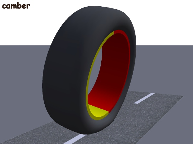
The complexity of simulating a tyre results from the fact that a tyre is not a simple object. Its shape, structure and materials are optimised for the conditions in which it is expected to operate. The tyre designer must make the tyre provide good grip, predictable forces and low rolling resistance for a range of slip angles and camber variations, under greatly varying loads, speeds and temperatures.
Tyre construction
This paragraph is to explain the main elements in the structure of a radial tyre, in my own words, so you can follow my terminology in the following discussion.
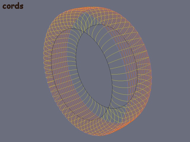
Many years of development led to the steel belted radial tyre as used on most passenger cars. The beads of the tyre are the two very strong and stiff circular steel cords which hold the tyre onto the rim, one on each side. The carcass (which forms the curved shape you see if you look inside a tyre) is formed from polyester cords laid radially (each cord runs from one bead, up the sidewall, across the tread area and down the other sidewall to the other bead). This flexible structure prevents the tyre from expanding like a balloon when inflated but allows it to deflect naturally when loaded, the sidewalls easily bulging outward to allow a flat contact patch to form. Between the carcass and the tread (but not in the sidewalls) is a steel belt consisting of at least two layers or plies of steel cords laid at an angle of around 20 degrees from the circumferential direction. The steel is highly resistant to stretching and stops the contact patch region deviating too much from the direction of the rest of the belt. The belt also prevents the tyre from expanding when speeds get high and retains the proper car tyre shape. The carcass and belt plies are encased in a matrix of rubber which keeps the cords in the right place, stops them rubbing against each other, provides damping and keeps the air in. The tread is a thick layer of rubber which covers the belt and is made of a different rubber compound, because it is designed with concerns such as grip and wear resistance.
|
|
Tyre design
The tyre designer can adjust many different parameters to produce a tyre with specific characteristics. At what angle should the steel cords be laid? How thick should the polyester and steel cords be? What spacing should there be between each cord? How many plies should there be in the belt? How deep will the tread be? What rubber compound should be used in the tread or other regions? What size and shape should the tread blocks be? The answers to these questions will depend on many requirements, such as the maximum speed, the maximum load, intended tyre life, operating temperature range, desired handling characteristics, tradeoff between grip and rolling resistance, types of surface that the tyre is designed for and so on.
LFS model
The improved LFS tyre model has gone through various stages of development. The starting point was a mathematically based, simple model that produced the combined lateral and longitudinal forces by looking at the deflection of an area of tread as it moves from the front to the rear of the contact patch. In the terminology of tyre models I think you could describe it as a "brush model including the effect of camber". It was able to provide some quite pleasing driving characteristics. The most obvious fault was an inability to correctly handle large camber situations, that do come up for various reasons even in a car simulator. So we moved to something more like a "tread simulaton model" which considered the tread in more detail, with a slightly higher computation cost. That was better to drive again and could handle large camber, but the forces due to camber were exaggerated because the model didn't properly take into account the flattening of the contact patch. Another problem was that even if the tread simulation is made quite accurate, the results still do not resemble the forces of a real tyre well enough. This is because the behaviour of a real tyre is influenced greatly by the deformation of the carcass and belt.
|
|
The belt deforms under load to form a flat contact patch. How much force does the tyre return for a given vertical deflection and how long is the contact patch in that case? The length of the contact patch is very important for the forces and torques the wheel produces when there is any lateral or longitudinal slip. The area and load distribution affect the contact patch pressure and therefore grip. These are important values but cannot be found from a simple mathematical formula. How much does the contact patch direction deviate from that of the wheel, when a self aligning torque is present? How much does the tyre deflect laterally for a given lateral force and how linear or curved does the tyre appear when that happens, so how much of an effect like camber does that distorted tyre produce? These have an important effect on the amount of force for a given slip angle, again greatly affecting the car's handling and feel.
For a given tyre, the answers to some of these questions may be near constant (linear relationships) while others are curves (non-linear relationships) and most of the values change with tyre pressure. The answers cannot be found by simple reasoning or geometry, because they depend on the tyre's shape and structural rigidity. So I turned to a high resolution simulated tyre to look for the answers. This special test rig simulation is not a model that can be used in game because it takes several seconds to simulate one tyre's movement in one second of real time. By modelling the stiffness of the carcass, belts, rubber and air pressure, the complex non-real-time model can provide insight into the deformations of a tyre of given dimensions and internal construction. The idea is that if this model is made as realistic as possible, and the in-game real-time model is made to produce a close approximation of the complex model, then that is one way to make the driveable cars behave like real ones.
|
|